Reasons Behind Bangkok High-Rise Collapse During Earthquake

The real reasons behind the collapse of an under-construction high-rise building in Bangkok, Thailand, during the Myanmar earthquake can only be understood after a detailed investigation. In this article, I’ll focus on some of the possible reasons based on the social media video evidence.

This article is purely for educational purposes and doesn’t necessarily represent my employer’s views.

Bangkok’s skyline has been growing for many years to accommodate the population growth as a result of the booming economy. About 9 million people lived in the city as of 2021, and nearly 17.4 million lived within the surrounding metropolitan region. The oldest high-rise building of Bangkok, 495 feet tall, 43-story Baiyoke Tower I, was constructed in 1994. The current tallest building in the city is the 1033-foot-tall Magnolia Waterfront Residences, which has 70 floors. The design and construction of skyscrapers are not something new to the city’s industry.

Bangkok’s skyline in January 2017, with 78-story tall King Power Mahanakhon . CC – Wikipedia

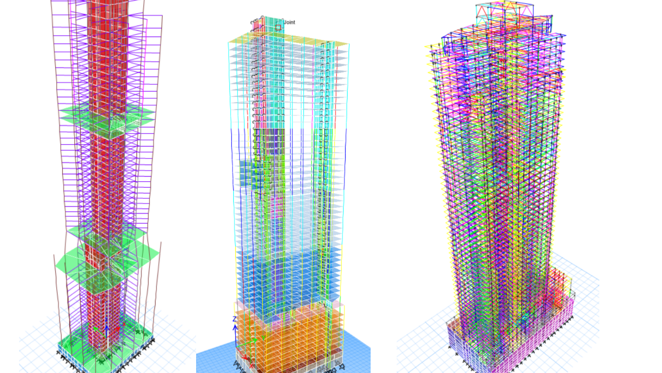
On 28 March 2025 when a 7.7 magnitude earthquake hit Mandalay in Myanmar. Bangkok, which is about 1000 km away from the earthquake epicenter, was shaken by earthquake waves. Many structures collapsed, and most (almost all) of them were older buildings that were (probably) not designed with the latest seismic codes. One of the collapsed buildings was a 33-story (449 feet tall) new, under-construction building. The building’s structure was topped out, so arguably, the seismic-force-resisting system (SFRS) was already in place. Based on the available data, this building’s SFRS consisted of a concrete core-wall system.

The video below shows how tall buildings behave under far-field and near-field ground motions differently. Far-field ground motions have long-period waves that excite the primary modes (first few modes) of a building. Under such conditions, the tall buildings experience large lateral drifts, leading to the development of plastic hinges in shear walls at the bottom stories.

I compiled a video (below) with 3 different views of the collapsing tower with my best effort to align the movement. Here are the three angles,

1. The left view, although difficult to see, shows the concrete shear wall core moving vertically down.

2. The center view shows a wide-angle view of the building’s front with concrete columns. Note that the first columns to fail were at the level 2nd from the top. NOT the top slender columns.

3. The right view shows the zoomed-in view of the top floors. You can observe that the center of the building starts to move vertically downward. This is an indication that the failure started either in the middle columns or the shear wall core.

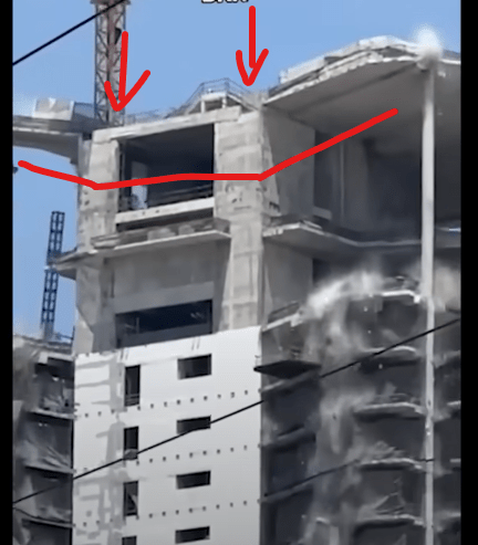
Here is a screenshot of another video that showed the top floors from the shear wall side of the building. The image shows the shear wall core moving downward, pulling the post-tensioned slabs with it, while the concrete columns hold them up. This caused the slab to bend, straining the slab-column and slab-wall connections. This could have caused punching shear failure in the slabs at the column support. The concrete dust at the column-slab connection is an indicator of such failure. You don’t see such dust at the slab-wall connection.

Now, based on my observation above, here is my hypothesis of the sequence of events that happened within 2 seconds,

Event 1. The concrete shear wall core lost its gravity load-carrying capacity at the base. This caused the vertical downward movement in the entire core. The next few paragraphs focus on what could have happened at the base.

Event 2. The core tried to pull the prestressed concrete slabs with it, causing punching shear failure at the columns closest to the core.

Event 3. The moving slabs started to pull the columns on the other side of the building, increasing the column shear demand. The short columns on the 2nd level from the top failed in shear, starting a complete story collapse.

Event 4. Breaking of prestressing tendons could have caused a shockwave, leading to stress amplification in other columns and amplifying the progressive collapse.

Event 5. While the upper floors started to collapse, the tall columns at the bottom story failed in shear.

A question that baffled me is, “If the shear wall core at the base failed first, why didn’t it cause a failure in the bottom columns first instead of the columns at the top, as seen in the video?” I am not sure. It could be that the prestressed slab got disconnected from the shear wall due to excessive rotation.

Here are two scenarios that could have played out to cause the shear wall core to collapse.

Scenario 1

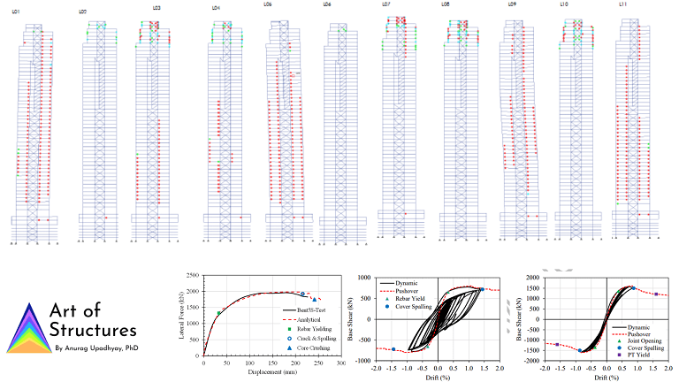
When subjected to lateral forces, the concrete shear walls are designed to develop a plastic hinge over the lower stories, generally at the base. A plastic hinge is a combination of rebar yielding and concrete damage, which dissipates the input seismic energy via controlled damage under cyclic loading. Mild-steel rebar has a great ability to stretch beyond its yield point before it fractures. This quality is a result of the thermo-mechanical process used to manufacture the rebar. Countries around the world have standards set in place to achieve a desired amount of “stretch” in the rebar to be sold for construction.

But, what if the rebar used in the construction is faulty and fails prematurely (see the stress-strain curve in the image below)? When pushed laterally by the seismic forces, the shear wall experiences overturning motion. As a result, the group of rebar at the extreme end of the wall undergoes stretching and yielding, thus developing a plastic hinge at the wall base.

With a faulty rebar fracturing without achieving a large strain after the yield point, the concrete at the other end of the wall would crush immediately. This, in some cases, could even lead to the loss of the gravity load-carrying capacity of the shear wall.
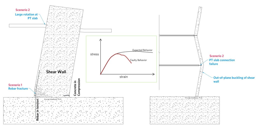

Scenario 2

Another hypothesis is that the PT slab to the shear wall connection failed due to excessive rotation. Once the slab is detached, the clear height of the shear wall increases almost twofold, making it vulnerable to buckling. The buckled shear wall core could collapse with such a high axial load. The collapsing core would pull the prestressed slabs down, leading to slab failure (punching?) at column supports. With such a failure on multiple floors, a collapse mechanism brings the entire building down vertically instead of overturning. Such a mechanism is used for controlled demolition of buildings (see video below).

Of course, these are just the hypotheses for now. Hopefully, the research community will find the answers soon. What do you all think about the collapse? Coming up with possible theories is a great way to learn. You should have them too, and start discussion groups.

We will talk about more structural analysis in the next newsletter.

Cheers,
Anurag Upadhyay, Ph.D.

Leave a comment

Codes and Guidelines for Performance-Based Seismic Design – Part 1: Introduction

In a previous edition I mentioned that the limitations in the code-based structural design approach led to the innovation of the performance-based seismic design (PBSD) procedure. This, along with advancement in computation power, paved a way for engineers to utilize nonlinear time-history analysis to assess (nearly) true structural behavior. However, this required advanced knowledge of structural behavior and analysis techniques, which was (still is) quite rare.

“Performance-based design is an alternative approach,
specifically permitted under Section 104 of the International Building Code, which permits building officials to approve any design or means of construction on the basis of satisfactory evidence that the completed construction will be capable of providing equivalent protection to the public as designs that conform to the code’s prescriptive requirements.”

– Ron Hamburger & John Hooper (NASCC: The Steel Conference) Full Article


We all know that advocating for a procedure, which can only be utilized by only a handful of structural engineers, is not a great idea. There are a number of people involved in bringing a building to life,

1) Architects
2) Structural Engineers (EOR)
3) Seismic Peer Reviewers
4) General Contractors (GC)
5) Authority Having Jurisdiction (AHJ) to approve the design and permit
6) Developers/Owners

All of the mentioned above should understand how reliable a building design procedure is.

Who will peer review the seismic design carried out by the EOR? It is crucial that the peer reviewers have a good knowledge of nonlinear analysis.

General contractors have to deal with a significant amount of financial uncertainty while construction. What if they trust a design procedure that the AHJ or the permit officials fail to understand? This could lead to financial loss caused by delays and redesign.

Authorities (AHJs) need to understand how the nonlinear analysis and verification of seismic behavior is done. Otherwise, they may not even allow such design procedure in their city (jurisdiction).

Developing community supported guidelines on performance-based seismic design (PBSD) helped spread the knowledge and increase trust. Researchers and practicing engineers have been working for many years to develop codes, guidelines, and research documents to educate the larger structural engineering community.

Ron Hamburger, one of the pioneers, explained the history of PBSD really well in this video. I encourage you to also watch the other videos in this lecture series. My future posts will have a different theme and will not repeat the information in these videos.

Structural analysis and design is only one side of PBSD procedure. Seismology and Geotechnical engineering are equally important in simulating a realistic seismic performance of structures.

There are many codes (you must follow) and guidelines (good practices) available that we utilize in designing buildings with PBSD. We will explore them in the next edition of this newsletter. Here is what you can look forward to,

Part 2 – A brief introduction of the codes and guidelines with their applicability.
Part 3 – Software tools and workflows

Share this article with your friends and colleagues. Start your learning groups where you can grow together.

Cheers,
Anurag Upadhyay, Ph.D.

Leave a comment

Why is nonlinear structural analysis time consuming?

I developed 65 nonlinear analysis models in 2024 for various projects at Tipping. These projects were a mix of new design and seismic retrofit. After seeing my LinkedIn post, many engineers reached out to me wondering how I could do it despite nonlinear analysis being a time-consuming process.

Nonlinear structural analysis is the basis of a performance-based design (new or retrofit) procedure. It is a time-consuming process with a lot of possibilities for errors. In today’s post, I’ll talk about a few major reasons that make this process time-consuming.

1. Setting up the Nonlinear Model

This step takes the longest time and the most engineering effort. Ideally, this step is broken into multiple sub-steps such as gathering historical information, calculating component properties, importing properties into the software, etc. But, to talk about the challenges, I’ll combine all the challenging parts of this step into one.

To begin with, the engineer has to justify what structural components will be modeled with nonlinear behavior. Some “primary” structural components are designed to dissipate the input seismic energy through nonlinear action. For example, flexure in moment frame beams, coupling beams, column hinges, and shear wall hinges. These will definitely be modeled with a nonlinear material model. However, these components are (generally) not expected to exhibit significant nonlinearity in shear behavior.

However, the engineer on record (EOR) can decide to utilize the nonlinear shear behavior in these components to benefit the design. The EOR has to justify this behavior using calculations, engineering judgment, and a rigorous peer review.

Calculating beam hinge properties is quite straightforward. You just have to follow ASCE 41 backbone inputs based on the sectional design. The beam hinge behavior (almost) stays consistent during an earthquake. The nonlinear behavior of the structural components with varying axial loads is difficult to quantify.

For a seismic retrofit project of an existing building, gathering information on the material properties (concrete, rebar, structural steel, weld) is also an important step. ASCE 41 provides default lower-bound material strength for historical materials.

Historical structural drawings sometimes have shocking structural detailing. Sure, it must have made sense 70 years ago. Some of the structural detailing will definitely not qualify the current code provisions. You have to be really careful while making assumptions about the structural capacities.

Material Details in Historical Drawings

2. Ground Motion Selection and Scaling

A licensed Geotech engineer is tasked to select a set of representative ground motions scaled to the design response spectrum. The structural engineers can, sometimes, perform this step for concept phase studies. I have seen cases where we ran the analysis with the selected ground motions only to find large drift results for one or two ground motions, flagging them as statistical outliers. We then had to request a revised set of ground motions. But, the exercise could easily consume up to one week of the work schedule.

3. Analysis Convergence Issues

You have finished developing the nonlinear analysis model which works fine for modal and gravity (dead load) analysis. But, convergence issues start to appear as soon as you start running the nonlinear time-history analysis. Now you have to find out what is causing the non-convergence by looking at the mode shapes for possible anomalies, understanding the deformed shape produced by the incomplete analysis, reading the log file for warning messages, or worst: replacing the nonlinear components with linear elastic behavior one by one to find out what component type is causing the non-convergence.

Refresher: The analysis software runs multiple internal iterations at each analysis step to find a solution where the internal forces are balanced with the external ones. This is referred to as “convergence”. If the program is unable to find a solution, it accepts the error within a tolerance limit provided by the engineer. If it accepts a large error at each step,

“Convergence issues start to appear as soon as you start running the nonlinear time-history analysis.”

4. Design Iterations/ Re-design

Engineering design is iterative. You know the drill for the elastic design, assume the structural system, pick parameters, calculate design forces, perform component design, iterate until converge to final sizes. A Performance-based design process also deals with re-design but not as many as the elastic design. You analyzed the nonlinear building model using a suite of 11 ground motions and found that some components have exceeded their acceptable rotation/strain limit. Now you have to redesign these components and re-run all those analysis again. Do it until all the structural components in your building satisfy the acceptance criteria.

How many time do you have to do it? It all depends on your workflow. You can carefully choose a workflow that could reduce the iterations. At Tipping, we have run nonlinear time-history analyses for projects still in their concept phase. We did it because we could. Our workflow allows us to quickly create nonlinear models and post-process the results. I have also seen projects that are too large to do this in any phase. I have had nonlinear models of 50+ story buildings that took 5 days to finish a suite of 22 ground motions, and required 3 design iterations to get to a satisfactory design.

Planning to include soil-structure interaction in your nonlinear model? Be very mindful.

5. Peer review

All your work (design, nonlinear models, assumptions, code compliance, etc.) is reviewed by one or more independent reviewers appointed by the authority having jurisdiction. Once a week or bi-weekly, you send your work to the reviewers and receive a response the week after. Do we need a peer review? Absolutely! A nonlinear design method has so many uncertainties associated, that a peer review process is important to eliminate any biased engineering judgment. Peer reviewers are helpful and provide valuable comments. I have seen peer review comments actually saving time and effort, thus saving money.

Although a PBD approach is more expensive and time-consuming, it results in better structural design in most cases. Understanding nonlinear analysis helps innovate structural design.

Share this article with your friends and colleagues. Start your learning groups where you can grow together. I will talk more about nonlinear analysis in my next article.

Cheers,
Anurag Upadhyay, Ph.D.

Leave a comment

Why more structural engineers should learn nonlinear analysis.

Challenging existing guidelines has always been the catalyst for innovation, in any industry. Structural engineering is also not untouched by this magic. The evolution of buildings in modern times has seen a large shift from brick and stone masonry in the early 19th century to the marvels we see today designed with reinforced concrete and steel. This change is an outcome of the collective effort of the engineers, architects, and developers who dared to envision something better than what the building codes allowed them to design.

For example, the commercial building height limit in the early 19th century US was set to 130 feet (Height of Buildings Act of 1910), mostly due to firefighting considerations. Somehow, these limitations were picked up by the building design codes and also became a part of the structural design guidelines. Few questioned this limit at some point, used the fundamentals of engineering calculations to challenge this notion, and encouraged the amendments. While reading may make it seem simple and obvious, it must have taken a fair amount of effort to convince the authorities.

The above example is only one of many instances where having a deep knowledge of structural behavior has led to innovations. You can only imagine the efforts behind designing the first concrete tilt-up building and explaining it to the people involved. How about the first mass timber high-rise structure?

I think all these examples are a kind of performance-based design, with the idea of utilizing the first principles to design a structure beyond the code recommendations. In early 2000, structural engineers started to use nonlinear analysis methods to show the code-level performance of tall building structures with an optimized and economical lateral-force-resisting system, which was not allowed in ASCE 7. The building developers loved this idea since it led to significant material costs. The added design fee was offset by this monetary savings. The engineers and researchers involved in the process developed guidelines for this alternative design procedure.

“The building developers loved this idea since it led to significant material costs. The added design fee was offset by this monetary savings. “

Recently, some innovative structural engineers have utilized the idea of rocking mass-timber walls with energy dissipation as a lateral-force-resisting system in buildings. There are so many different implementations of this concept, for example, a rocking CLT wall assembly with butterfly fuses for panel-to-panel connection, and a post-tensioned timber wall with U-shaped energy dissipators at the ends. These ideas were successfully developed using a performance-based design utilizing nonlinear analysis.

You can see how a deep understanding of structural systems and nonlinear analysis has helped companies to innovate and become industry leaders. Can more projects around the world utilize a performance-based design? Absolutely! That is why more engineers should learn the concepts of nonlinear analysis.

Does it mean some engineering companies with expertise in performance-based design and nonlinear analysis could lose opportunities due to increased competition? Maybe for simple projects. But, I think this could lead to more innovations by these industry leaders. Almost all structural engineers in the world use the same elastic design method but Architects and developers still prefer a handful of names like Arup, WSP, SOM for unique buildings. Engineers at companies like Tipping, Degenkolb, and Holmes are consistently innovating in seismic retrofit and new structural systems due to a large pool of engineers on their team familiar with nonlinear analysis methods. Moreover, countries around the world require their own unique structural solutions utilizing local materials, focused on serving the local communities. Even if they don’t use it to design structures regularly, they should be able to help their building design codes evolve with the help of their discussions.

My goal for the year 2025 is to encourage more engineers to learn the concepts of nonlinear structural analysis to prepare for future innovations. I’ll share my journey and learning in this newsletter Art of Structures. If you have made it this far in today’s article, thank you for your support! Leave a comment if you want to discuss specific topics.

Anurag Upadhyay, Ph.D

Leave a comment

1.1 – Basis of Design

What is a Basis of Design (BOD) Document?

The basis of design document is an essential part of the performance-based seismic design documentation. The purpose of a BOD Document is to,

  • State deviations from code requirements (exceptions/enhancements). For example, if you have utilized the results from a latest research to verify the design methodology of coupling beams, it should be referenced in the BOD document.
  • Describe methods justifying deviations from the code requirements by explaining your thought process and approval from the peer review committee.
  • Content includes descriptions of structural systems, design procedures, performance objectives, modeling methods, and acceptance criteria.
  • Should be a stand-alone document with references to required details.

Scope and Presentation

Document is standalone with all the possible references that were used to carry out design and analysis for this particular project. No presentation of structural engineering results are included in this document.

BOD is included in the design drawings for building owner reference, especially if code exceptions are taken.

Incorporation in Drawings

The engineer should include the BOD in the design drawings for future reference, particularly if code exceptions are made. It is also highlighted in architectural building site permits in some jurisdictions.

Submission and Review

The BOD is submitted for peer review and local governing authorities. The process of review and modification to the BOD occurs early in the design process. Sometimes BOD is also revised through the design process to align with the final design.

Here is the Basis of Design document for the building “Salt Tower” we are designing.

Basis of Design for Salt Tower

1. Project Description

The Salt Tower is a new 42-story mix use building in downtown Salt Lake City, Utah (US). The building will provide retail space on the first two floors, office suites on 15 floors, and residential spaces with a mix of studio, 1-bedroom, 2-bedroom, and 3-bedroom apartments for the rest of the floors. The top 3 floors contain private luxury residences utilizing the entire floor area.

The structural systems for the various building components are summarized below:

1.1 Foundation

The foundation system consists of a single mat foundation supporting gravity and lateral elements. The mat foundation is designed for hydrostatic pressures. Foundation elements are anticipated to range from 36” thick to 84” thick dependent on demands.

To maintain support on shallow foundations, additional over excavation of the site is required to reach bedrock and remove existing Tolman substructure as required. The over excavated area shall be filled with on-site crushed concrete and mixed with 20% on-site native soils as recommended by the geotechnical engineer of record.

1.2 Gravity Framing

The substructure is primarily concrete construction, including concrete mild-slabs spanning between concrete columns and basement walls. Where spans/ loading exceeds the limitations of flat slab, wide-shallow beams are used to supplement. This selection is based on the requirements to retain significant lateral earth pressure from the east side of the site, as well as the need to support significant landscaping loads at Level 1. In addition, the shallower structural depth compared to steel construction will benefit the overall program due to the MEP routing below grade.

The gravity system for the super structure consists of 8” post-tensioned nominal weight concrete slab spanning between concrete columns and the core walls. Vertical columns consist of a combination of 24” square reinforced concrete columns on an approximate 24-ft x 24-ft grid system.

1.3 Lateral-Force-Resisting System

The lateral force-resisting system (LFRS) consists of a concrete core wall system with coupling beams spanning along building Y-direction. The base shear from the core wall system is transferred to the mat foundation at the seismic base level.

2. Building Codes and Exceptions

Purchase the course to get the full access to the following contents,

Material Properties
Seismic Performance Objectives
Development of Nonlinear Structural Model
Selection and Scaling of Ground Motions
Nonlinear Time-history Analysis (NLTHA)
Understanding NLTHA Results
Final Design Checks

If you have already purchased this course, log in and get full access to this course.